Description
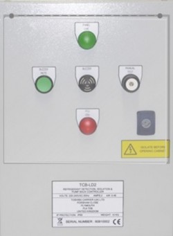
This new system can incorporate both an external and internal sensor monitoring systems to determine the level of refrigerant in the atmosphere and flowing within the system itself. All refrigerant leak detection and pump back products are CE certified.
As VRF systems become larger, supplying multiple indoor units, the refrigerant volume that flows within the system will increase. In the unlikely event of a refrigerant leak, it is possible that, if the room is small enough, the concentration level of refrigerant inside a room/office could become harmful to the occupant. Previously Toshiba stipulated that if the concentration level of the refrigerant could exceed 0.44kg/m3 that an opening be created with an adjacent room, or to fit a locally supplied mechanical ventilation device, combined with a gas leak detection device. The new “Refrigerant Leak Detection and Pump Back Products” will provide a solution to this potential issue, providing both an indication of a refrigerant leak (in accordance with EN378, where the refrigerant concentration level exceeds 0.44kg/m3) and the mechanical isolation and pump back of refrigerant from the indoor side to the outdoor unit.
Function Summary
1. External leak detection (LDS1 or LDS2 sensors) and Pump Back: When the sensor is activated (refrigerant concentration level exceeding (0.44Kg/cm2) an L30 fault code is displayed on both local and central remotes. The L30 fault code is also identified by the CDU via the TCC link network, activating the LD2 control module. The system will then enter a pump back operation (similar to that of test cool operation) returning refrigerant from the indoor side to the CDU. CDU isolation is achieved via dedicate isolation valves fitted to the main pipe work. On completion of the pump back a P15 fault code is displayed on both the 7 segment display on the CDU and the local/central remotes (note for FCU that detected refrigerant leak, a L30 fault code will be displayed locally).
2. Internal leak detection and Pump Back: is completed via the continued monitoring of key system temperatures and pressures. When the software identifies that the refrigerant level within the system has dropped, a signal is sent from the CDU to the new LD2 control module activating a pump back operation (similar to that of test cool operation), returning refrigerant from the indoor side to the CDU. CDU isolation is achieved via dedicate isolation valves fitted to the main pipe work. On completion of the pump back a P15 fault code is displayed on both the 7 segment display on the CDU and the local/central remotes.


